How to Draw Letters in Autocad 2016
Review the basic AutoCAD controls.
After you launch AutoCAD, click the Start Drawing button to begin a new drawing.

AutoCAD includes a standard tabbed ribbon across the top of the drawing area. You can access nearly all the commands presented in this guide from the Home tab. In addition, the Quick Access toolbar shown below includes familiar commands such as New, Open, Save, Print, Undo, and so on.
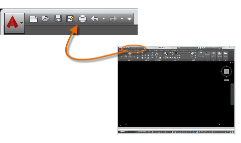
Note: If the Home tab is not the current tab, go ahead and click it.
The Command Window
At the heart of AutoCAD is the Command window, which is normally docked at the bottom of the application window. The Command window displays prompts, options, and messages.

You can enter commands directly in the Command window instead of using the ribbon, toolbars, and menus. Many long-time AutoCAD users prefer this method.
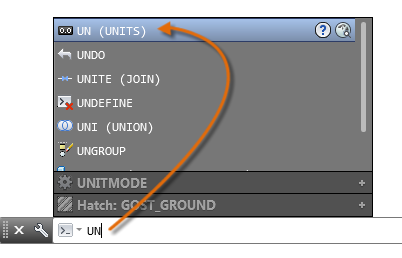
Notice that as you start to type a command, it is completed automatically. When several possibilities are available such as in the example below, you can make your choice by clicking it or using the arrow keys and then pressing Enter or the Spacebar.
The Mouse
Most people use a mouse as their pointing device, but other devices have equivalent controls.

Tip: When you look for an option, try right-clicking. Depending on where you locate your cursor, different menus will display relevant commands and options.
New Drawings
You can easily conform to industry or company standards by specifying settings for text, dimensions, linetypes, and several other features. For example, this backyard deck design displays two different dimension styles.
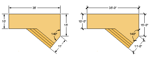
All these settings can be saved in a drawing template file. Click New to choose from several drawing template files:

- For imperial drawings that assume your units are inches, use acad.dwt or acadlt.dwt.
- For metric units that assume your units are millimeters, use acadiso.dwt or acadltiso.dwt.
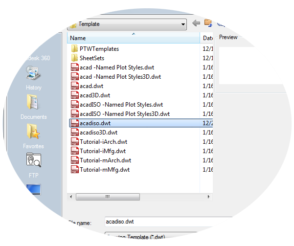
The "Tutorial" template files in the list are simple examples for the architectural or mechanical design disciplines with both imperial (i) and metric (m) versions. You might want to experiment with them.
Most companies use drawing template files that conform to company standards. They will often use different drawing template files depending on the project or the client.
Create Your Own Drawing Template File
You can save any drawing (.dwg) file as a drawing template (.dwt) file. You can also open any existing drawing template file, modify it, and then save it again, with a different filename if needed.
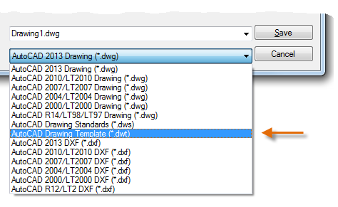
If you work independently, you can develop your drawing template files to suit your working preferences, adding settings for additional features as you become familiar with them.
To modify an existing drawing template file, click Open, specify Drawing Template (*.dwt) in the Select File dialog box, and choose the template file.

Important: If your company has already established a set of drawing template files, check with your CAD manager before modifying any of them.
Units
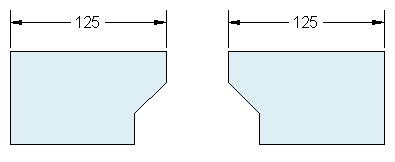
When you first start a drawing, you need to decide what the length of one unit represents—an inch, a foot, a centimeter, a kilometer, or some other unit of length. For example, the objects below could represent two buildings that are each 125 feet long, or they could represent a section from a mechanical part that is measured in millimeters.
Unit Display Settings
After you decide what unit of length that you want to use, the UNITS command lets you control several unit display settings including the following:
- Format (or Type). For example a decimal length of 6.5 can be set to display as a fractional length of 6-1/2 instead.
- Precision. For example, a decimal length of 6.5 can be set to display as 6.50, 6.500, or 6.5000.
If you plan to work in feet and inches, use the UNITS command to set the unit type to Architectural, and then when you create objects, specify their lengths in inches. If you plan to use metric units, leave the unit type set to Decimal. Changing the unit format and precision does not affect the internal precision of your drawing. It affects only how lengths, angles, and coordinates are displayed in the user interface.
Tip: If you need to change the UNITS settings, make sure that you save the drawing as a drawing template file. Otherwise, you will need to change the UNITS settings for each new drawing.
Model Scale
Always create your models at full size (1:1 scale). The term model refers to the geometry of your design. A drawing includes the model geometry along with the views, notes, dimensions, callouts, tables, and the title block displayed in the layout.
You can specify the scaling that is necessary to print a drawing on a standard-sized sheet later, when you create the layout.
Recommendations
- To open Help with information about the command in progress, simply press F1.
- To repeat the previous command, press Enter or the Spacebar.
- To see various options, select an object and right-click, or right-click a user interface element.
- To cancel a command in progress or if you ever feel stuck, press Esc. For example, if you click in the drawing area before entering a command, you will see something like the following:

Press Esc to cancel this preselection operation.
Source: https://knowledge.autodesk.com/support/autocad/learn-explore/caas/CloudHelp/cloudhelp/2016/ENU/AutoCAD-Core/files/GUID-5B6347C1-B458-4336-AB2A-C16AF161B755-htm.html
0 Response to "How to Draw Letters in Autocad 2016"
Post a Comment